
Page 11 - Ketterer – Brochure Motor Drives and Spindle Drives
P. 11
ø5.2 (2x) 72.2 21.4
15.3
ø45
40
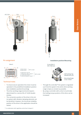
Pin assignment
View A
56 78
43 21
Technical notes
Installation position/Mounting
A
Screw M6x12 DIN 7380 (2x)
4. 8.
2. 1. 3, 5.
Motor black - Motor blue +
WST or ALEX
Hall sensor red +5V
Hall sensor violet, output 2 7. Hall sensor black -
Hall sensor green, output 1
WST or ALEX
Self locking ring SEEGER-KS3 (2x)
Mounting flange 3133.19-0001
▪ To ensure secure operation the motor must be operated in the predefined installation position (see installation position/mounting).
▪ The drive working range (nominal torque) is determined for a service life of 10,000 double strokes.
▪ The connection position of the drive in the ent- ire system with vibration damping elements can be beneficial. However, the functional reliability position of the drive in the application should be tested.
▪ ▪
Through the controller* the system is regulated such that the speed in the entire drive working range is kept as constant as possible.
By using a controller with a short-circuit brake the holding torque position of the drive can be increased.
* In combination with LogicData control box Compact-3
www.ketterer.de
121
1.6
5.2
115°
17°
Cable length 1000, incl. connector
115.5
ø19 137
Gear Motors
hex 6/7/9
