
Page 9 - Ketterer – Brochure Lifting Units
P. 9
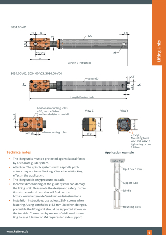
 3034.00-V01
Technical notes
Application example
12
24
9.5 12.5 44
8.5
3034.00-V02, 3034.00-V03, 3034.00-V04
Z
ø4.1 (2x)
4.5
Y
Additional mounting holes ø 3.6, max. 4.5 deep (double-sided) for screw M4
3
View Y
No mounting holes
▪ The lifting units must be protected against lateral forces by a separate guide system.
▪ Attention: The spindle systems with a spindle pitch
> 3mm may not be self-locking. Check the self-locking effect in the application.
▪ The lifting unit is only pressure loadable.
▪ Incorrect dimensioning of the guide system can damage
the lifting unit: Please note the design and safety instruc- tions for spindle drives. You will find them at:
https:// www.ketterer.de/en/downloads/instructions
Table top
Support tube Spindle
Mounting bolts
▪ Installation instructions: use at least 2 M4 screws when fastening. Using bore holes ø 4.1 mm (2x) when doing so, preferable the lifting unit should be supported above on the top side. Connection by means of additional moun- ting holes ø 3.6 mm for M4 requires top side support.
www.ketterer.de
191
ø20
Length E (retracted)
square22
Length E (retracted)
View Z
25.8
ø8
hex 6
25.8
ø20
ø4.8
Lifting Units
12
19
ø 3.4 (2x)
Mounting holes WN1452 K40x16 tightening torque 1.8 Nm
Input hex 6 mm
