
Page 7 - Ketterer – Brochure Lifting Units
P. 7
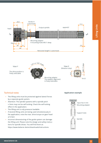
 29.5 Stroke H customized
17.5
              Input
Output spindle square22
                                                                                                                                                                       YX Mounting adapter
                                                                                                                                                                                                                                                                                                                                                 hex 6
44
View Y
11
4 mounting holes M5/ 5 deep
Retracted length E customized
2.5
  24
     View X (Rotation stop)
9
          The drive position is freely selectable
Technical notes
Mounting adapter
The adapter alignment is freely selectable
R 4.5
                  ▪ The lifting units must be protected against lateral forces by a separate guide system.
▪ Attention: The spindle systems with a spindle pitch
> 3mm may not be self-locking. Check the self-locking effect in the application.
▪ The lifting unit is only pressure loadable.
▪ If several lifting units are being used simultaneously in
the application, note the max. drive torque on gear head
of 3 Nm!
▪ Incorrect dimensioning of the guide system can damage
the lifting unit: Please note the design and safety instruc- tions for spindle drives. You will find them at: https://www.ketterer.de/en/downloads/instructions
Table top
Application example
  Input hex 6 mm Mounting adapter
Support tube
Spindle
www.ketterer.de
97
   1
r
°
o
0
2
3
5
1
°
a
n
g
l
e
16.5
M6/ 17 deep
16
Lifting Units
