
Page 19 - Ketterer – Brochure Motor Drives and Spindle Drives
P. 19
120
123
654
Technical notes
Load
59.5
45 20 35
Required direction
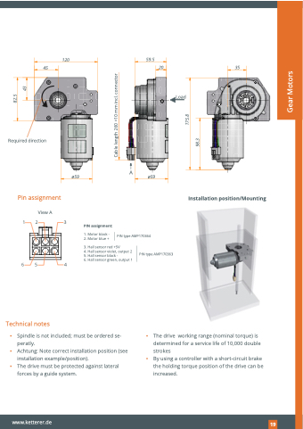
Pin assignment
View A
ø59
A
ø59
Installation position/Mounting
PIN assignment:
1. Motor black - 2. Motor blue +
PIN type AMP170364
3. Hall sensor red +5V
4. Hall sensor violet, output 2 5. Hall sensor black -
6. Hall sensor green, output 1
PIN type AMP170363
▪ Spindle is not included; must be ordered se- peratly.
▪ Achtung: Note correct installation position (see installation example/position).
▪ The drive must be protected against lateral forces by a guide system.
▪ The drive working range (nominal torque) is determined for a service life of 10,000 double strokes
▪ By using a controller with a short-circuit brake the holding torque position of the drive can be increased.
www.ketterer.de
129
Cable length 260 +10 mm incl. connector
98.3
175.8
82.5
43
Gear Motors
