
Page 13 - Ketterer – Brochure Lifting Units
P. 13
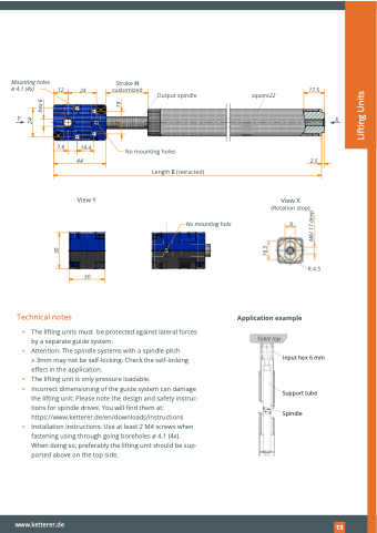
                                                                                                                                                                                                     Mounting holes ø 4.1 (4x)
Y
12
24
Stroke H customized
17.5
2.5
           Output spindle
square22
     X
      7.6 14.4 44
View Y
30
No mounting holes
Length E (retracted)
No mounting hole
View X (Rotation stop)
9
                                                                               R 4.5
           Technical notes
Application example
▪ The lifting units must be protected against lateral forces by a separate guide system.
▪ Attention: The spindle systems with a spindle pitch
> 3mm may not be self-locking. Check the self-locking effect in the application.
▪ The lifting unit is only pressure loadable.
▪ Incorrect dimensioning of the guide system can damage
the lifting unit: Please note the design and safety instruc- tions for spindle drives. You will find them at: https://www.ketterer.de/en/downloads/instructions
▪ Installation instructions: Use at least 2 M4 screws when fastening using through going boreholes ø 4.1 (4x). When doing so, preferably the lifting unit should be sup- ported above on the top side.
Table top
              Input hex 6 mm
Support tube Spindle
                                                www.ketterer.de
153
   30
16.5
M6/ 17 deep
24
hex 6
Lifting Units
19
