
Page 11 - Ketterer Torque-Motors t-Rex
P. 11
BLDC-Motors
t-Rex 3200 I-44-89 L12 S2 DH
Rated voltage Rated current
Rated torque
Rated speed
Shaft power (output) Max. efficiency
Idle speed
No-load current
Stall torque
Starting current at idle speed Torque constant
Speed constant
Motor parameters
Terminal resistance (phase to phase) Terminal inductance (phase to phase) Rotor inertia
Number of poles
Interconnection of the motor Number of coils per phase Interconnection of coils Direction of rotation
Note: Max. ambient temperature = 40 °C, controller-specific At the nominal point (TU = 20°C), controller-specific
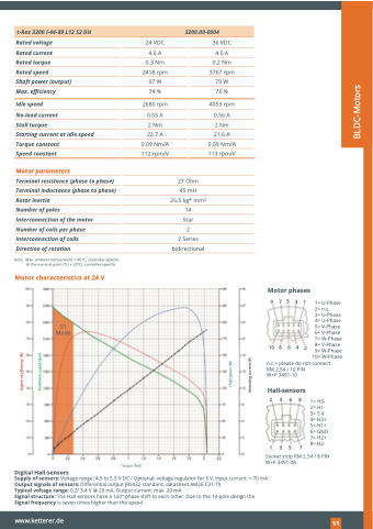
Motor characteristics at 24 V
S1 Mode
3200.00-0004
24 VDC 4.0 A
0.3 Nm 2418 rpm 67 W 74 %
2680 rpm
0.55 A
2 Nm 22.7 A 0.09 Nm/A 112 rpm/V
36 VDC 4.0 A
0.2 Nm 3767 rpm 79 W 76 %
4053 rpm
0.56 A
2 Nm 21.6 A 0.09 Nm/A 113 rpm/V
27 Ohm 45 mH 26.5 kg* mm2 14
Star
2
2 Series bidirectional
Motor phases
97531
10 8 6 4 2
1= U-Phase 2= n.c.
3= U-Phase 4= U-Phase 5= V-Phase 6= V-Phase 7= W-Phase 8= V-Phase 9= W-Phase
Shaft power (W)
Degree of efficiency (%)
Rotational speed (rpm)
Recording current (A)
10= W-Phase n.c.= please do not connect
RM 2,54 / 10 PIN W+P 3491-10
Hall-sensors
Torque (Nm)
Socket strip RM 2.54 / 8 PIN W+P 3491-08
Digital Hall-sensors
Supply of sensors: Voltage range: 4.5 to 5.5 V DC / Optional: voltage regulator for 5 V, Input current: < 70 mA Output signals of sensors: Differential output (RS422 standard, datasheet AM26 C31-TI)
Typical voltage range: 0.2/ 3.4 V @ 20 mA, Output current: max. 20 mA
Signal structure: The Hall sensors have a 120° phase shift to each other. Due to the 14-pole design the Signal frequency is seven times higher than the speed
2468
1357
1= H3- 2= H1- 3= 5 V 4= H3+ 5= H1+ 6= GND 7= H2+ 8= H2-
www.ketterer.de
121
