
Page 17 - Ketterer – Brochure Lifting Units
P. 17
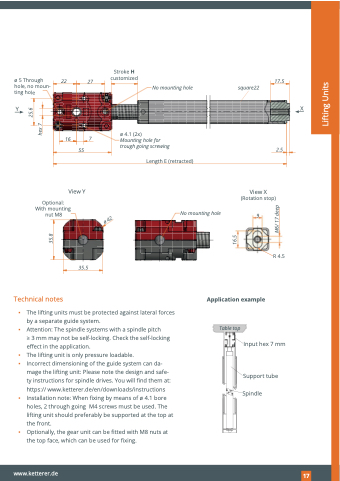
                                                                                                                                                                                                     Stroke H
22 27 customized 17.5
No mounting hole square22
YX
                            16 7 55
View Y
ø 4.1 (2x)
Mounting hole for
trough going screwing 2.5
   Optional: With mounting nut M8
Length E (retracted)
22           No mounting hole
View X (Rotation stop)
       9
                                                                                                                   R 4.5
              35.5
 Technical notes
Application example
▪ The lifting units must be protected against lateral forces by a separate guide system.
▪ Attention: The spindle systems with a spindle pitch
> 3 mm may not be self-locking. Check the self-locking effect in the application.
▪ The lifting unit is only pressure loadable.
▪ Incorrect dimensioning of the guide system can da-
mage the lifting unit: Please note the design and safe- ty instructions for spindle drives. You will find them at: https:// www.ketterer.de/en/downloads/instructions
▪ Installation note: When fixing by means of ø 4.1 bore holes, 2 through going M4 screws must be used. The lifting unit should preferably be supported at the top at the front.
▪ Optionally, the gear unit can be fitted with M8 nuts at the top face, which can be used for fixing.
Table top
          Input hex 7 mm
Support tube Spindle
    www.ketterer.de
197
   ø 5 Through hole, no moun- ting hole
ø 42
35.8
16.5
M6/ 17 deep
hex 7
25.6
Lifting Units
